this year I would like to propose to my students the construction of an electric guitar (actually usable) using scrap materials. the task seems daunting to me but not impossible (I hope). first of all, if any forum users have already had similar experiences in this regard, it would be nice to take advantage of my post to delve deeper into the subject.
for now I am sharing the info that I have managed to gather so far (but I believe it is incomplete, especially regarding the electrical part).
the shape of the guitar (central body) is quite relative. what matters is the length of the neck and the way it is divided into frets (and this depends directly on the actual length of each vibrating string, i.e., from the bridge at the headstock to the bridge on the central body. to emulate the glorious guitars of the past (e.g. fender, stratocaster, etc.), so-called GUITAR PLANS are easily available online, scale assembly diagrams (they are usually made in A4 format; therefore they would need to be enlarged to a 1:1 scale - but I haven't understood how to do it with mathematical precision!?!)
for the PICK-UP, I am thinking of using 3-4 microphones from some old landline telephones. I used one (as a test) on a recycled BERIMBAU (a one-string bass used in capoeira ensembles). the electrical signal it produces is not particularly powerful but when sent to an amplification system and adjusted properly, the sound quality is appreciable (but adjustment is anything but simple). I would like to understand how to boost this signal before it is sent to the amplification system. maybe with a battery? and how should it be connected?....in essence, the electrical circuit I want to create should consist of 3-4 pickups, a pickup selector, and at least one potentiometer for volume control. I believe potentiometers and selectors can be found at any electrical/electronic component retailer....but how do I connect them? that is all
i hope that this post can be enriched with useful info hello everyone
It seems a bit pricey to me... But an electric guitar pedal? There are some diagrams on the internet. They are easy to make and the components don't cost that much.
as for components, asking around a bit, I would be looking at around 30 euros (pickguard, volume potentiometer, tone potentiometer, 1 bag of 10-15 capacitors). I haven't included the pickup because instead I would like to use some piezo-electrics salvaged from old watches or old telephone microphones.
i would ultimately like to create a proper product... also because if the built guitar could truly play like a guitar, we (my students and I) could really think about building them in series for the school students!
i think i have more or less understood how the connections should be made....i would like, for safety's sake, to involve an "external expert", obviously as part of a project and with adequate compensation.
do you happen to know anyone in Turin and/or the surrounding areas?
thanks, simone! it's a great compliment and i don't know if i deserve it. i do what i can. i always try to propose experiences that i would have loved to have been proposed to me (years ago). and then...let's face it...i have a world of fun too! :-D
Trust me, it's just the truth. In middle school, I had teachers who just came to warm the benches and only made us do something with the recorder. Music class was for me the hour of total depression, while for others, it was one more hour of break.
I would have greatly enjoyed taking part in activities like those you occasionally propose here on the forum.
my exhausting theoretical and practical research is finally starting to take shape.
i am only missing a few more pieces to have sufficient "mastery" of the situation.
i would like confirmation from those among you who might know more than me.
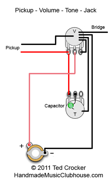
for the electrical part, i would like to consider one potentiometer for volume and one for tone.
i found the attached schematic online.
correct me if i am wrong: RED wire: positive; BLACK wire: negative?
and finally, the pickup that i would like to use is a HUMBUCKER type; it has a single wire, whose copper part is covered by a mesh which i imagine is what is colloquially called GROUND. regarding polarity: copper wire: POSITIVE? GROUND: NEGATIVE?
There are actually always two wires, but the ground is used as a shielding mesh. It wraps around the signal wire to limit external electromagnetic interference; in any case, that mesh at the ends must be soldered to a ground (0 reference).