Plugins always follow the simulation of analog outboard gear, so digital equalizers also refer back to existing types of analog equalizers.
There are essentially 4 types of Equalizers:
- Parametric (considered the best)
- Semi-parametric
- Peaking
- Graphic
Parametric equalizers are those in which you have several "parameters" available to set, which is why they are called "parametric." They usually have 4 intervention bands (lows, mids, high-mids, highs). Normally, the Q factor is only present in the central bands, while at the lows and highs, you can adjust the frequency and gain factor with a shelving filter.
Semi-parametric ones are those where the Q factor is fixed.
In peaking equalizers, you can only decide the gain factor because all other parameters are fixed.
Lastly, graphic equalizers, in which there are a certain number of bands upon which you can intervene on the gain factors.
Logic's EQ is an extended parametric one. In digital, frequency controls can easily be added without complicating any circuitry. The cleanest sound in analog is the one that passes through the fewest possible circuits because with every interaction with an electronic component "something happens" that modifies the signal. Obviously, in digital, this problem does not exist. The signal is a data stream and the application of filters is a process that has to do with processing time but not with the quality of the output signal. To put it simply, if I were to add a very large number "n" of equalization bands while still leaving the gain at 0, the signal would undergo no modification in the EQ output, but I would have increased the latency caused by the large number of operations the CPU would have to perform on the signal. If I therefore added 100,000 digital filters, I would experience no change in the signal, except for an increase in latency (which is inversely proportional to the machine's computing capabilities); if I added 100,000 filters in an analog device, the output signal would undergo significant changes.
Low-pass, high-pass, shelving, and peaking filters.
The low-pass filter, as the name suggests, allows frequencies below the cutoff frequency to pass undisturbed. Normally, the "cutoff frequency" is considered the point at which the signal is attenuated by -3dB. In some professional analog outboards, manufacturers define the cutoff frequency when the signal is attenuated by -1dB (this is always noted in the technical data sheet).
The high-pass works exactly the opposite of the low-pass, so let's not waste time there.
The shelving filter is similar to the low-pass and high-pass, but the attenuation does not tend toward -∞. The filter begins to attenuate from the cutoff frequency until it reaches a horizontal asymptote; the maximum or minimum attenuation/boost reachable depends on the specifications of the filter and can range from -12/+12dB up to even -24/+24dB.
The peaking filter is the classic one recognizable by its bell shape, in which the frequency declared on the Pot defines the center band.
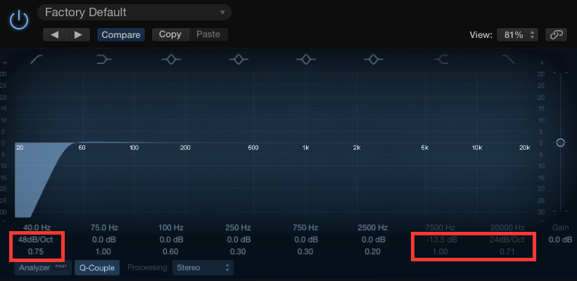
Coming now to the photo you posted...
On the high-pass (the first one on the left), you have the possibility to adjust the cutoff frequency, the filter selectivity in dB/octave, and finally the Q factor, which is unusual for high-pass/low-pass filters. In fact, since the high-pass/low-pass does not have a center band, increasing the value of the selectivity factor (Q factor) causes the derivative value to increase for values coming from the right at that point (the cutoff frequency); consequently, a positive peak is created to the right of the cutoff value. For the low-pass, the reasoning is totally analogous.
Then you have the shelving filters. Since we said that the attenuation band tends toward a horizontal asymptote, modifying the Q factor will result in an inflection point at the minimum and an oblique asymptote at the maximum.
Lastly, the Peaking filters. In this case, dealing with a bell shape, the Q factor will simply widen or narrow the bell, making the filter less selective and more selective respectively...
All this said in plain words... I hope I have cleared up your doubts.